Multifunction Video Display system integrates full-motion video from all sources at all vehicle crew stations
By Mr. Sean Jellish and Mr. Brian Wilson
A crew of four combat engineers is buttoned up in a Medium Mine Protected Vehicle (MMPV) Type II, moving down the road in search of suspected explosive hazards, with a mission to ensure that the route is safe for a convoy to travel. Each crew member has a set mission and, other than the driver, each is most likely using an enabler or sensor to help find the hazards. Each Soldier can only see what that sensor displays, requiring him or her to alert the rest of the team to what they see. But wouldn’t it be better if the rest of the team could see that information too, rather than just hear about it? Wouldn’t it be better to tie all these sensors together, to give the truck commander all the information his crew has so that he can make decisions quicker and with more confidence?
With the evolution of the improvised explosive device threat, the Army has seen a proliferation of independent control systems in the route clearance MMPV Type II crew compartments. These “vehicle enablers,” such as imaging sensors, weapon systems and communications equipment, come with their own proprietary and unique operator stations, which can be viewed and controlled only by the Soldiers assigned to them. All of these different operator stations limit room for future capability growth and create integration challenges. Even if all the stations could fit in one vehicle, they’d require too many displays for a single operator to view and control effectively.
To address these challenges in the forthcoming MMPV Type II program of record (POR), the U.S. Army Research, Development and Engineering Command’s Communications-Electronics Center (CERDEC), a subordinate organization to U.S. Army Materiel Command, partnered with the Product Manager for Assured Mobility Systems (PdM AMS) to rapidly develop a software and hardware architecture called the Multifunction Video Display (MVD). PdM AMS comes under the Army Project Office for Mine Resistant Ambush Protected Vehicles, assigned to the Program Executive Office (PEO) for Combat Support and Combat Service Support.

SPEED TEST To test for system latency—the delay between input and outcome—an oscilloscope compared the speed of the signal as measured directly from the initial event with raw video processed through the camera, media converter, server and display. Tests indicated that latency under full load was well within required specifications.
The MVD system efficiently distributes images and sensor control to all crew stations within a vehicle, resulting in a single touch-screen display for each crew station capable of viewing and controlling all vehicle enablers, and creating a seamless common interface across all enablers. This allows capability growth without increasing display size, weight and power (SWAP) requirements. Adding a new enabler no longer requires the addition of an enabler operator’s station. MVD technology is completely government-owned and -developed, is hardware-independent, enabling it to run on numerous platforms, and has a plug-and-play VICTORY (Vehicle Integration for C4ISR/EW [command, control, communications, computers, information, surveillance and reconnaissance/electronic warfare] Interoperability)-based architecture. The software can run on any platform.

EYES EVERYWHEREThe graphical user interface of the MVD system establishes a common monitor and interface to view and operate many simultaneous real-time video feeds. The system can also act as a digital video recorder, allowing for the capture and playback of video sequences and snapshots.
MULTIPLE EFFICIENCIES
MVD improves mission capability by increasing operator efficiency and situational awareness and reducing SWAP requirements. Operator efficiency improves first by keeping the operator focused on one display that presents him or her with an identical view of each vehicle enabler from the common user interface all the enablers share. Similarly, the training burden is reduced with consistency across operator controls. The operator has only one interface to learn and a common set of controls for all enablers, now and into the future.
Previously, full-motion video could only be viewed by a single crew member with the enabler’s dedicated display. With MVD, any crew member can view video from any or all enablers simultaneously and in real time. With additional eyes on each video feed, situational awareness increases proportionally. Finally, the single integrated MVD system obviates the need for dedicated processing and display hardware, reducing SWAP requirements.

MOVING INTO FOCUS An MVD plug-in enables use of high-magnification sensors, which means that crews can perform roadway and roadside threat detection at extended ranges while on the move.
AGGRESSIVE TIMELINE, AGGRESSIVE PLAN
The MVD project originated in a conversation between the CERDEC Night Vision and Electronic Sensors Directorate (NVESD) and PdM AMS at a forum hosted by the U.S. Army Engineer School related to capability production document (CPD) vehicle requirements for the MMPV Type II POR. The overall CPD required a common, intuitive display to view and control all vehicle enablers at all crew stations simultaneously in real time, with the capacity for future growth. NVESD had accomplished a related display effort called Multi-sensor Graphical User Interface, which could be augmented to meet that MMPV Type II single display requirement. The timeline for development was aggressive as the result of the MMPV Type II fielding schedule.
To be considered for insertion into the MMPV during its U.S. Army Test and Evaluation Center testing (currently ongoing), NVESD and PdM AMS had to demonstrate a working prototype system within six months, followed quickly by a six-month prototype refinement period to create a more ruggedized version.
As a first step, NVESD conducted an architecture study to determine how best to meet the overall project goal. NVESD identified three target system architectures. NVESD designed the software prototypes for each architecture and collaborated with hardware vendors to design the hardware prototypes that would demonstrate the architectures. Common to each approach was the need to convert the MMPV Type II legacy analog camera data to digital and then fit the data into the available bandwidth for each display. The aggregate bandwidth of all the different vehicle-enablers is roughly three times more than most common commercial off-the-shelf interfaces can handle.

PUTTING IT TOGETHER The system architecture used in the MVD system provides robust, distributed processing for redundancy, speed and room for future growth without the need for costly reconfigurations.
The three architectures varied mainly in where they collected imagery and how they disseminated it to the displays. A centralized architecture collected the images at a central server with dedicated image-capturing hardware that compressed the imagery and sent it out to the displays. A distributed architecture had image-capturing hardware in each display to capture a subset of the images, which it compressed and passed to the other displays. A network-centric approach used stand-alone media converters to capture the imagery and a server switch to compress it and send it to the displays.
The network-centric architecture was deemed the best of the three. It has ample hardware redundancy to survive various kinds of hardware failure as opposed to the centralized approach, which would be crippled by the failure of the central server. It minimizes the number of components required in the displays, keeping them thin and light for rapid vehicle ingress and egress. And, as the vehicle shifts away from analog sensors, the media converters can be removed and new digital sensors can tap directly into the server switch. Finally, this approach conforms to the Army’s move toward network connectedness with the introduction of the VICTORY standard for communicating between systems within a vehicle and the Integrated Sensor Architecture (ISA) for sharing information between sensors and systems in a tactical environment.
Over the course of the MVD system development, NVESD worked closely with multiple hardware vendors to transition each of the system architectural components from laboratory-grade prototypes to full military standard, conduction-cooled, production products capable of operating in the extreme environments of the MMPV Type II at minimal cost.
DELIVERING THE SYSTEM
The evolution of the system server switch set the stage for the entire MVD procurement strategy. After completing the initial system demonstrations, it was time for the ruggedized solution. While researching similar hardware acquisitions on other government projects, NVESD found that the ruggedized servers used by the Project Manager for the Warfighter Information Network – Tactical (PM WIN-T) met the needs of MVD almost perfectly. PM WIN-T, assigned to the PEO for Command, Control and Communications – Tactical (PEO C3T), was purchasing its servers using the Common Hardware Systems 4 contract of PEO C3T’s PM for Mission Command, a contract open to all DOD customers to procure tactical hardware and services. PdM AMS is testing this procurement mechanism, which would greatly reduce the time necessary to purchase hardware, for use with MVD.

TIGHT QUARTERS The current crew station includes separate displays for each of the enablers in use, including imaging sensors, weapon systems and communications equipment, limiting room for future capability growth and creating integration challenges.
A PATH FOR GROWTH
The MVD software is hardware-independent and operates on any of the three architectures with minor modifications. MVD design is novel in that it uses a modular plug-in-based architecture, which means that new enabler systems can be added without modifying or recompiling any of the existing code. This is a tremendous cost savings as the hybrid threat is continuously adapting to defeat-strategies, requiring new vehicle-enablers. MVD software comprises many thousands of lines of code that government personnel at NVESD authored quickly to meet the aggressive development schedule. The code has been through multiple rounds of static analysis as well as code coverage testing to ensure that every line operates as intended without errors. In addition, a mobile platform version of the system for Android devices will allow an operator to continue using enablers while dismounted from the vehicle.
The system uses industry standards for interfaces and data formats, including both VICTORY and ISA, enabling it to communicate with current and future systems internal and external to the vehicle platform. Along with image display, the MVD system can also act as a digital video recorder, allowing for the capture and playback of video sequences and snapshots. The MVD system currently allows for the full control of several of the MMPV Type II enablers and display of nine separate camera feeds. The system has demonstrated robustness in testing with 14 full-motion video feeds captured simultaneously and displayed in real time—nearly five times more enabler feeds than any single configuration of a typical MMPV Type II platform. This is the key demonstration that provided the assurance PdM AMS needed to select the MVD system as the display solution for its MMPV Type II POR.
With all enablers viewed and controlled through MVD and plenty of processing headroom, MVD has great potential for future growth into previously unreachable areas that use a number of separate enablers. For example, MVD contains a plug-in that can slew a high-magnification sensor to a specific spot simply by touching the wide field-of-view video displayed on another enabler, allowing operators to perform roadway and roadside threat detection at extended ranges while moving. MVD can also transform the outputs of all enablers into the same geospatial coordinate system and has the processing power to perform detection and tracking algorithms on them, which means it can be used algorithmically to aid operators in detecting threats.

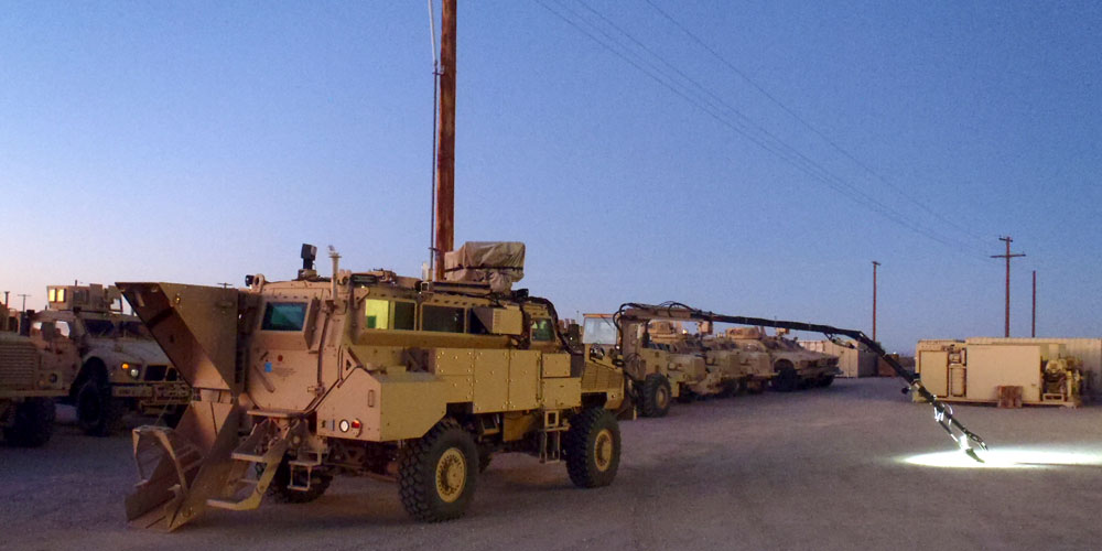
ON A MISSION The CERDEC Night Vision and Electronic Sensors Directorate and the Product Manager for Assured Mobility Systems rapidly developed the Multifunction Video Display, a software and hardware architecture that distributes images and sensor control to all crew stations within the MMPV Type II, shown here performing roadside threat interrogation activity. (Photos and images courtesy of CERDEC)
CONCLUSION
With the multiple improvements it represents in capability, as well as the built-in processing headroom that provides for future capability growth, MVD was PdM AMS’ natural choice to be the display system in the MMPV Type II POR. It will improve communication within the MMPV Type II vehicle crew and decrease the time spent searching for suspected explosive hazards, allowing route clearance teams to become more efficient while keeping them safer when performing their mission.
This system has the potential to tap into many of the combat developers’ future capability production document programs and tie them together while improving the way that route clearance will be done in the future. The stovepiped method of adding new capabilities and sensors is gone, replaced by the “tablet-like” capability of the MVD. The benefits of the MVD system don’t stop there, either; MVD has the potential to affect all DOD ground vehicles with sensors by acting as the operator’s display, thereby achieving substantial SWAP reductions and saving money.
For more information, please contact Sean Jellish (sean.m.jellish.civ@mail.mil) or Brian Wilson (brian.j.wilson90.civ@mail.mil)
MR. SEAN JELLISH is the lead engineer on the MVD program at NVESD, Fort Belvoir, VA. He specializes in algorithm development, embedded processing, hardware and software architectures and mobile programming. He has an M.S. in electrical engineering and a B.S. in computer science and electrical engineering from the University of Virginia. He is Level III certified in systems engineering and is a member of the Army Acquisition Corps.
MR. BRIAN WILSON is the engineering team leader for the system integration of route clearance vehicle enablers at PdM AMS. He holds an M.S. in engineering management from the University of Michigan and a B.S. in mechanical engineering from University of Detroit Mercy. He is Level III certified in systems engineering and is a member of the Army Acquisition Corps.
This article was originally published in the July – September 2015 issue of Army AL&T magazine.
Access AL&T is the premier online news source for the Army Acquisition Workforce.
 Click to Subscribe